Gaggiuino and Topology Optimization
This project was the final project for ME 581, Simulation of Multibody Dynamic. During this class, we learned how:
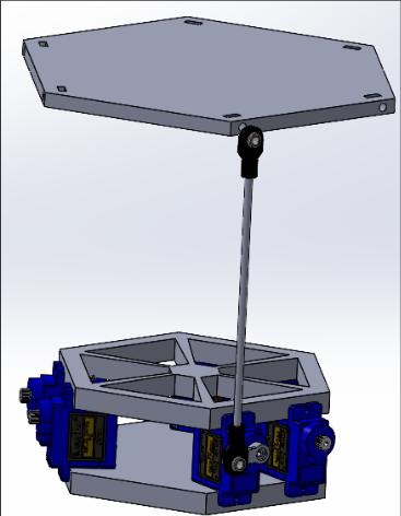
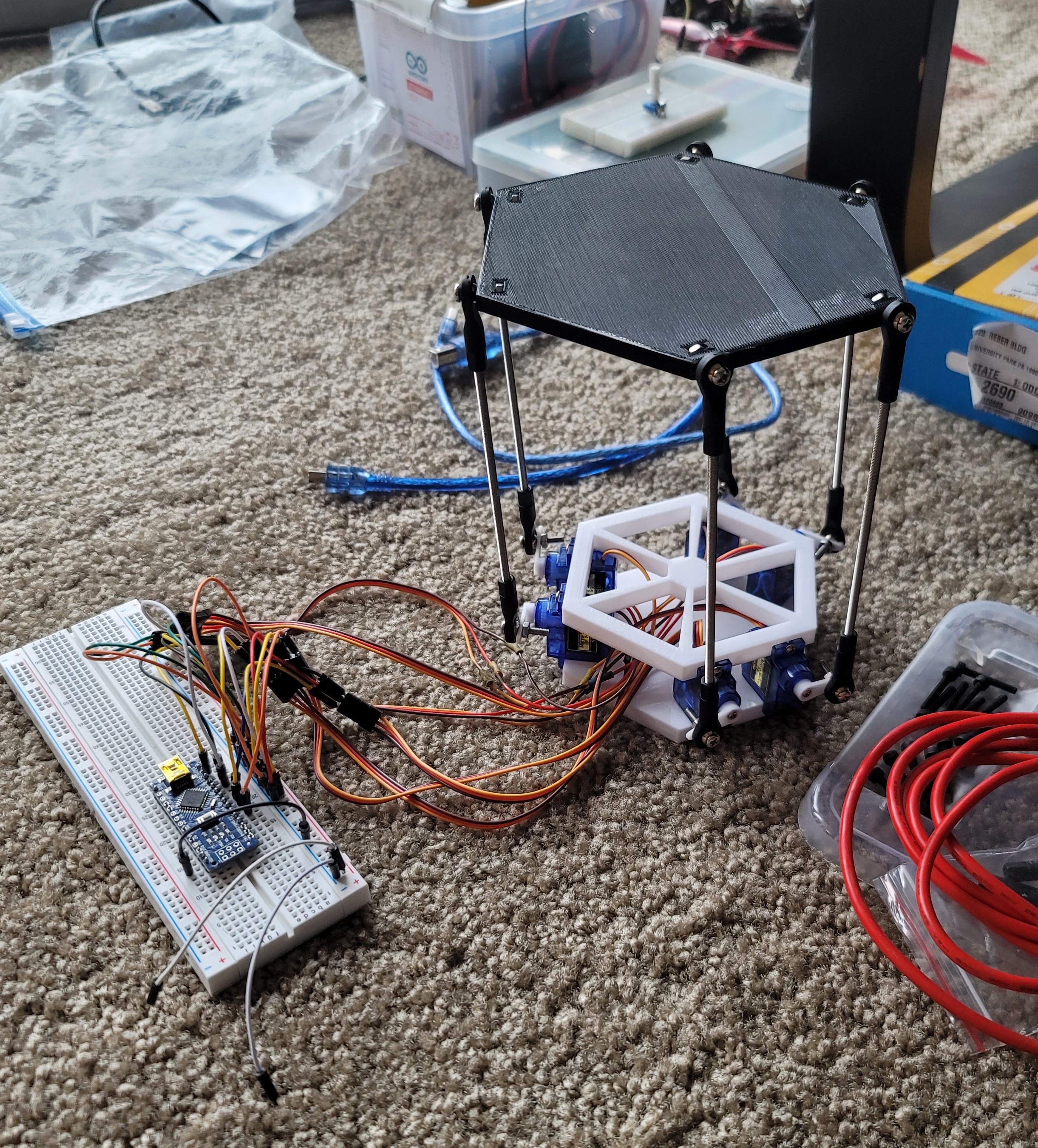
To begin this project I had to make decisions into what parts to use I decided with using SG90 servos as they are cheap and I have experience using them. So, I established the base of the design using these servos. I then used threaded rods and small ball joints to connect the platform to the servo horns. Once, I completed choosing the parts, designing the 3d-prints was very easy as the only requirements is that it could hold the servo motors and have a place to screw the ball joints to. I did have to be wary of the spacing between the motors and the mounting points of the platform, as I needed those dimensions for calculations later. The completed 3d design can be seen in the picture to the left.
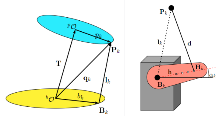
To get the platform working in the method I wanted, I used the knowledge we learned in class about getting the leg lengths to move the platform. The main difference between what we did in class was that I had to take into account the servo horns. Since I wasn't using linear actuators and using servos with a horn and a ball joint to produce linear motion I had to do some additional math. Thankfully, it wasn't difficult, and many other people have already successfully done this, useful to check my math.
Once I was able to calculate the necessary leg lengths I use a simple formula to get the needed servo angles. The rest of the code just moves the servos to the correct place. Moving the servos was completed just using the Servo library. Two of the most helpful images I found online that helped me with the code and the math can be seen on the right. The image with the two circles shows how the leg lengths are calculated, while the image with the servo horn is how the angle is calculated from the needed change in leg length.
Gaggiuino and Topology Optimization

Refitting the IVSG Mapping Van
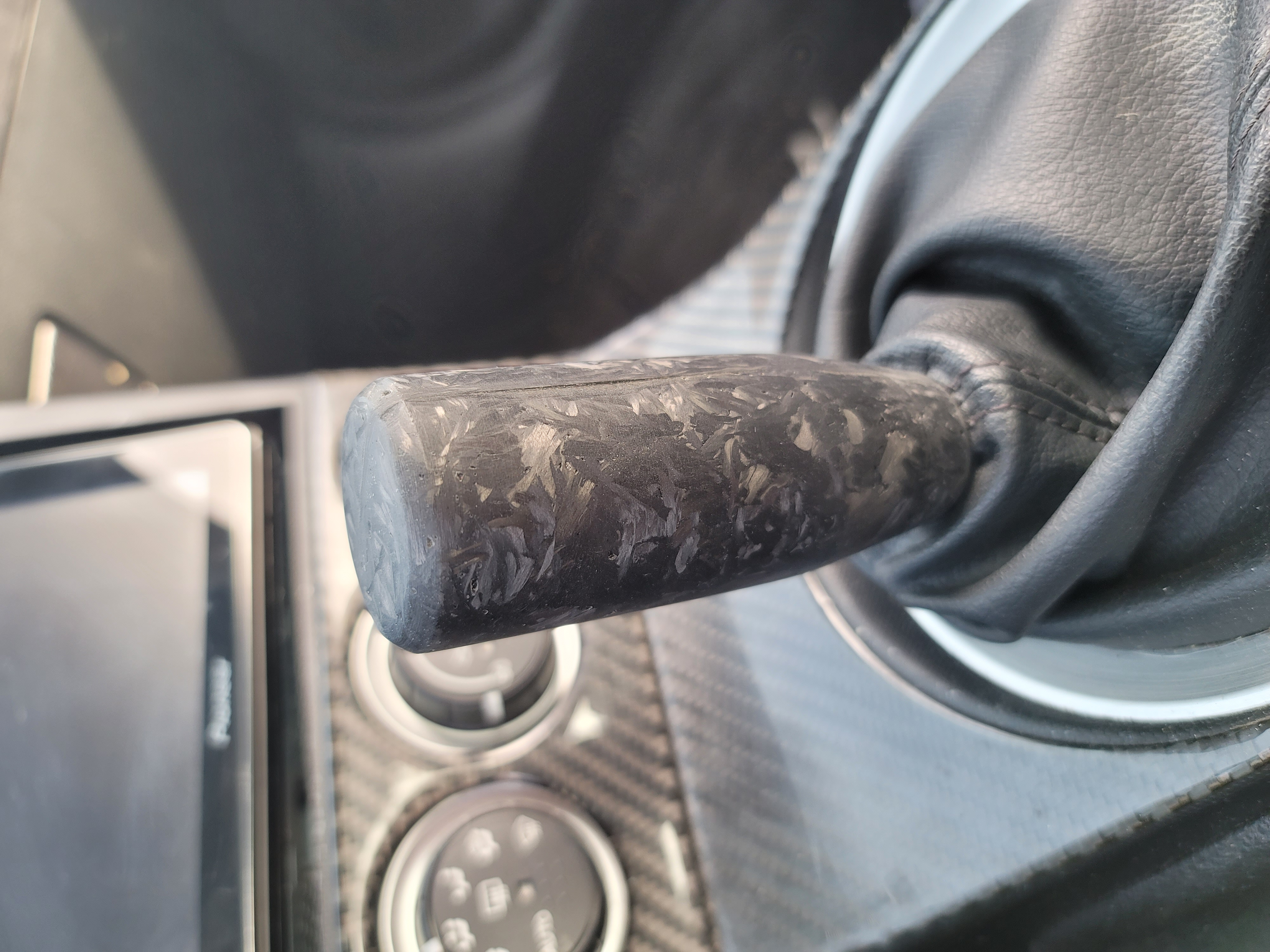
Forged Carbon Fiber Shift Knob
Serious collaboration or work inquiries only.